LC Connector
compact fiber patchingLC uses a 1.25 mm ceramic ferrule and familiar latch to align one fiber in a compact body. Duplex clips pair transmit and receive connectors for most Ethernet links.
LC provides density without relaxing optical discipline: inspect, clean and match the polish before every connection.
Anatomy of the connector
Use the supplied plate to identify the connector, then check the four details below before selecting, terminating or mating it.
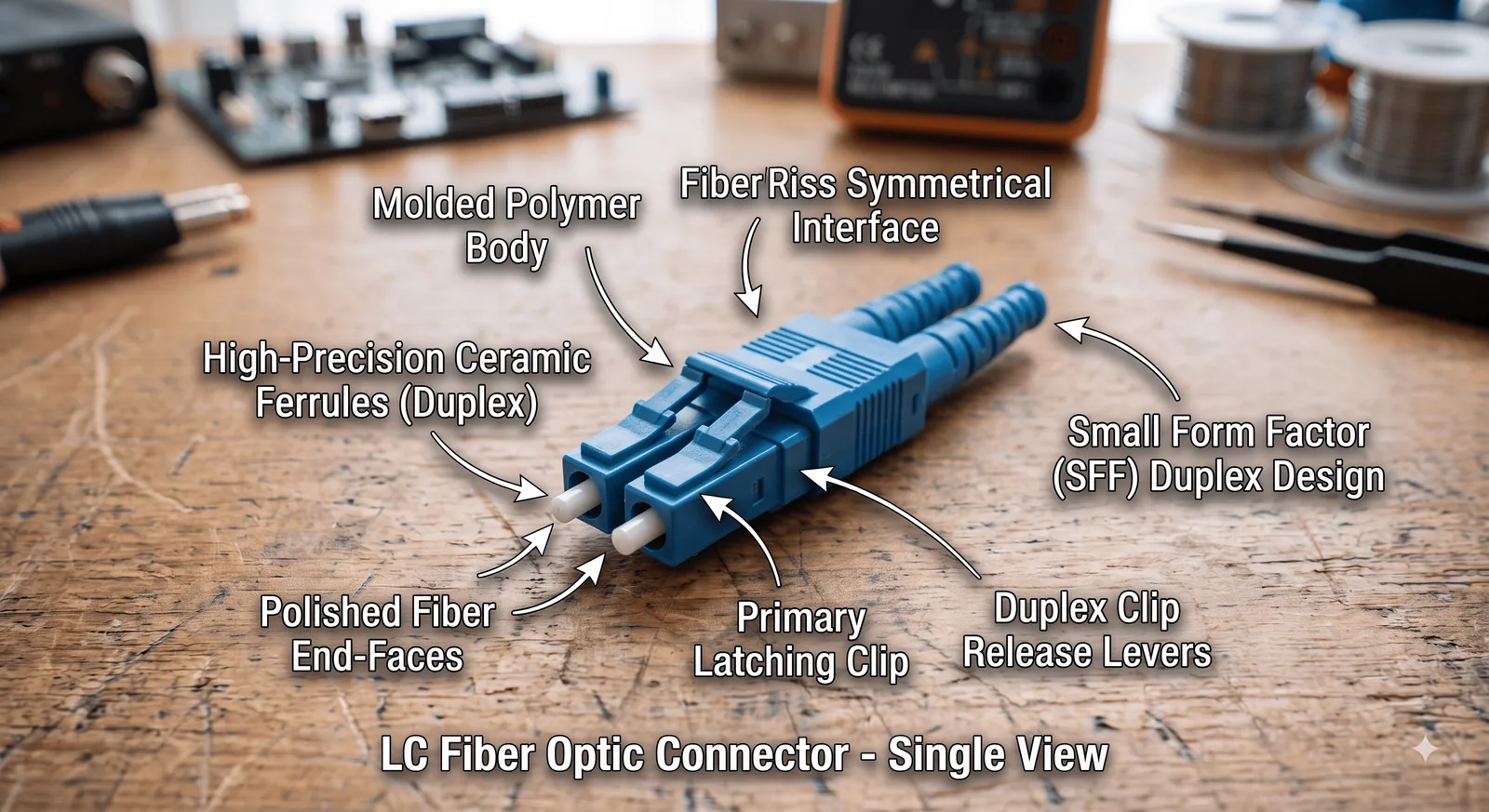
Four details to check before connection
The ceramic cylinder centres the bare fiber core with microscopic precision.
The keyed body controls orientation and protects the ferrule.
The latch retains the plug while a clip pairs transmit and receive fibers.
The flexible rear boot limits sharp bends where the cable enters the connector.
Where it is used
The connector body is only one part of a link. Cable type, signal, impedance or optical polish must match the equipment on both ends.
Duplex LC is standard on many 1G, 10G and higher serial optical transceivers.
Its compact body allows high port density in racks and enclosures.
Single-mode and multimode LC patching serves backbone and equipment links.
In cybersecurity & operations
Optical ports are sensitive physical interfaces. Protect the patch field and treat cleanliness, bend radius and laser safety as availability controls.
A dirty plug contaminates the socket and causes loss or reflection. Inspect, clean, inspect again.
Never mate blue UPC and green APC end faces; their polish geometry differs.
Verify transmit reaches receive when building or changing a duplex link.
Never look into a fiber or transceiver. Use an optical power meter and approved procedures.