STP Cable
balanced pairs inside a shieldShielded twisted-pair cable combines differential signalling with a metallic screen around the pairs. The shield improves immunity to electromagnetic interference, but only when the connectors, patch panels and bonding plan preserve a continuous, intentional path.
STP is a complete screened channel—not simply a heavier cable. Its benefit depends on shield continuity and correct bonding from one end of the link to the other.
Anatomy of the cable
Read the supplied diagram first, then follow the four layers below from the signal path out to the protective jacket and termination.
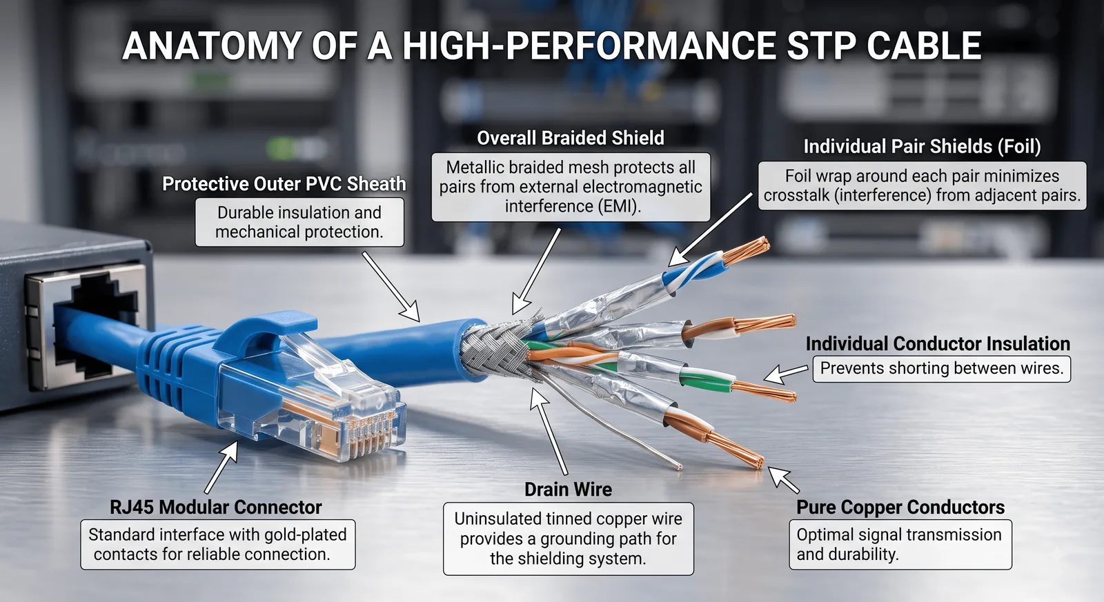
The four parts that make the medium work
Four balanced pairs carry Ethernet exactly as they do in unshielded category cable.
Foil and braid configurations reduce external noise and alien crosstalk.
Some designs include a conductor that makes the foil screen practical to terminate and bond.
A screened jack and patch panel maintain coverage and connect the channel to the bonding system.
Where it is used
The cable name is a family, not one universal specification. Pick the construction, connector and equipment for the actual link.
Screened cable protects links routed near drives, motors and other strong noise sources.
Cat6A screened systems can control alien crosstalk where many cables share a tray.
Predictable noise performance helps in facilities containing RF and high-power equipment.
In cybersecurity
A shield can improve availability by reducing interference, but poor bonding can create a new fault path. Follow the cabling and electrical standards for the building rather than improvising a ground.
An unshielded plug or patch cord breaks the screened channel and weakens the expected protection.
Incorrect earthing can create voltage differences and unwanted currents. Use the approved telecommunications bonding system.
Shielding does not stop physical taps or rogue endpoints. Apply the same port and access controls as UTP.
Crushing, tight bends and excessive pull force disturb pair geometry and screen coverage.
Use jacks, panels and cords designed for the same cable construction and category.
Test shield continuity as well as wiremap, length, loss and crosstalk on critical links.